SLUICE HILL
Construction of Sluice Hill
|
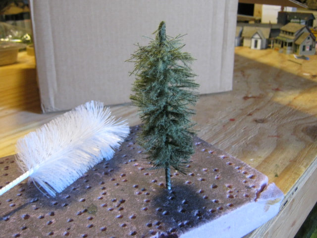
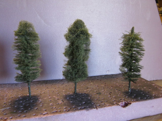
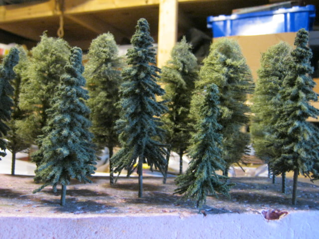
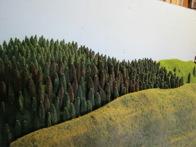
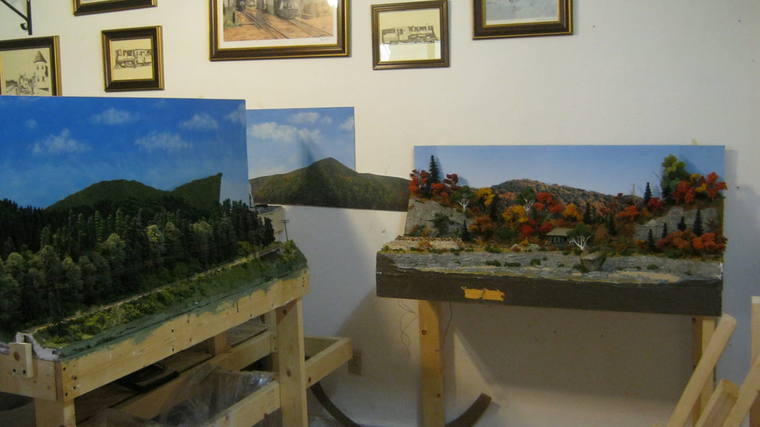
One of the layout design elements I wanted to emphasize for Sluice Hill was the density of the virgin Maine woods in the area at the time. Trees, trees, and more trees. An experiment was making my own version of bottle brush trees for thick pines. The three prototypes at right were the result, with the left-most of the three being the winning candidate.
|
|
|
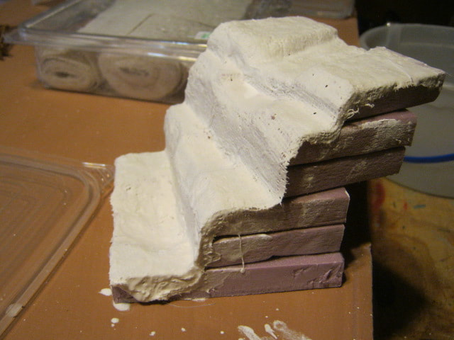
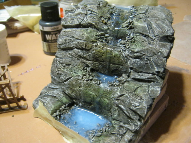
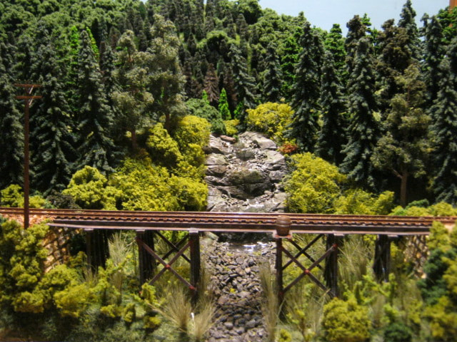
Another layout design element I wanted to use for Sluice Hill was "The Cascades", a beautiful waterfall that visitors to the Rangeley area were very impressed with.
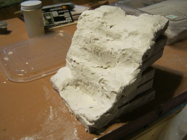
Built up foam 'steps' covered in plaster cloth formed the base to start with, then this was buttered with hydrocal plaster for carving into the bedrock that the falls would cascade down. |
|
|
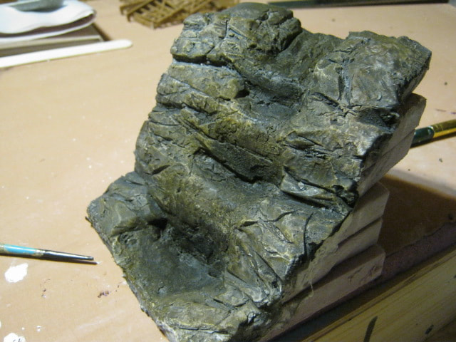
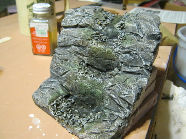
The granite was carved with a dull x-acto knife, which is a great re-purposing for blades instead of throwing them out. The granite finish was made with washes of diluted black, tan, and grey acrylic paint, then dry-brushed with "oyster white", which is what I weather virtually everything I do with. Algae was dry-brushed on, and then rubble added in.
|
|
|
The water was added using Woodland Scenics' Realistic Water, slowly pouring small amounts from the top of the falls and letting them flow down naturally. Using too much would cause a flood at the bottom.
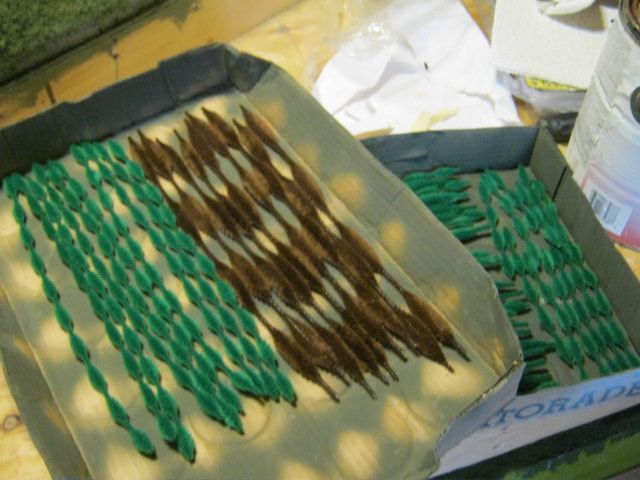
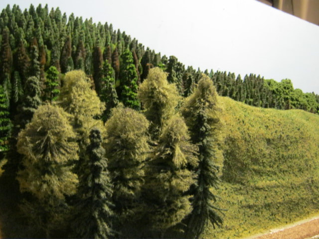
In between steps of building the falls, I made more pines and super-detailed ready-made trees with flocking. |
|
|
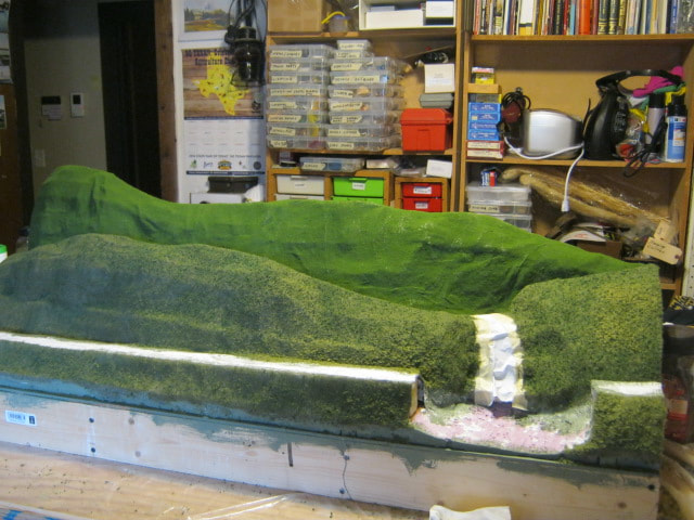
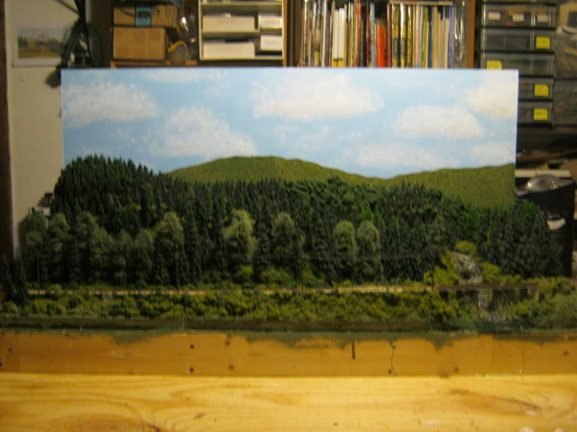
The base is an 18" x 48" framwork of 1"x4" lumber, topped with 1/4" plywood and foam board. The road bed is 1/2" plywood elevated on 1"x2" supports with a grade of 3%.
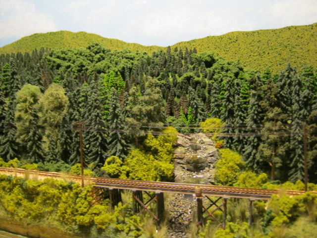
The hills are cardboard strip lattice covered with plaster cloth, and the falls was embedded into the hills when the plaster cloth went on. The near hill was covered with coarse ground foam, and the rear with fine ground foam. |

|
|
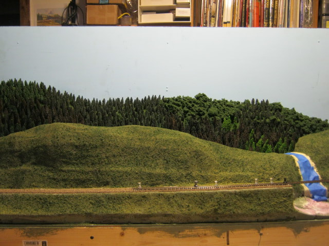
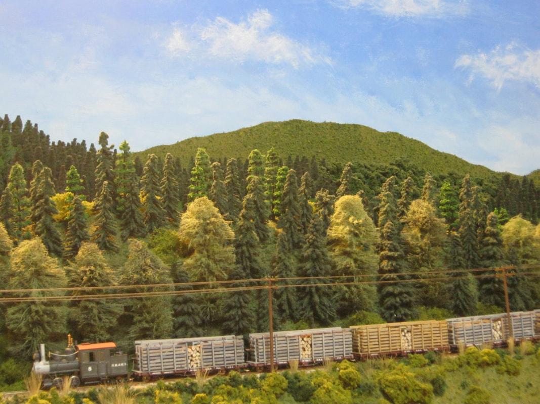
The trees for the rear hill were put on first. The majority are evergreens made from bump-chenille, spray painted various shades of olive and green. The deciduous trees were made by simply glueing on chunks of clump-ground-foam.
The trees on the rear hill give the forced perspective view of being much further back than the front hill. |
|
|
After the rear hill was populated with trees, the cork road bed and track were laid. The track was run completely across the gap at the falls. After the track was laid, then the majority of the large and detailed trees for the front hill were put on.
|
|
|
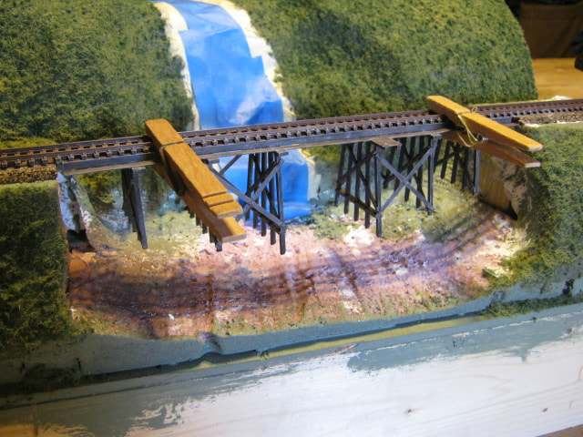
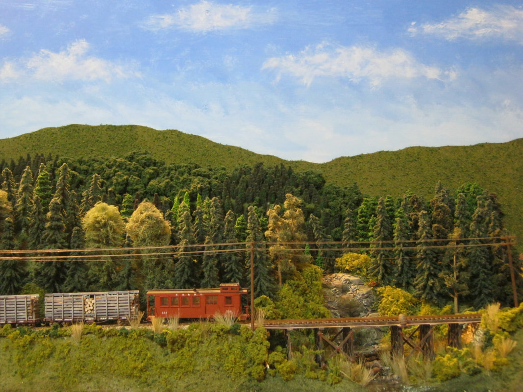
The trestle was built from some bargain bents from a box under a table at a train show. The rest of the timbers are Evergreen Plastics structural forms, and the structure was super-detailed with Grandt Line nut/bolt/washer assemblies.
After the bridge was epoxied to the track, the abutments and ground were built up to meet the bridge, and the rest of the scenery filled in. |
|
|
Once the scenery was all done, telegraph poles were installed, and the telegraph wire added by using Grand Central Junction E-Z Line.
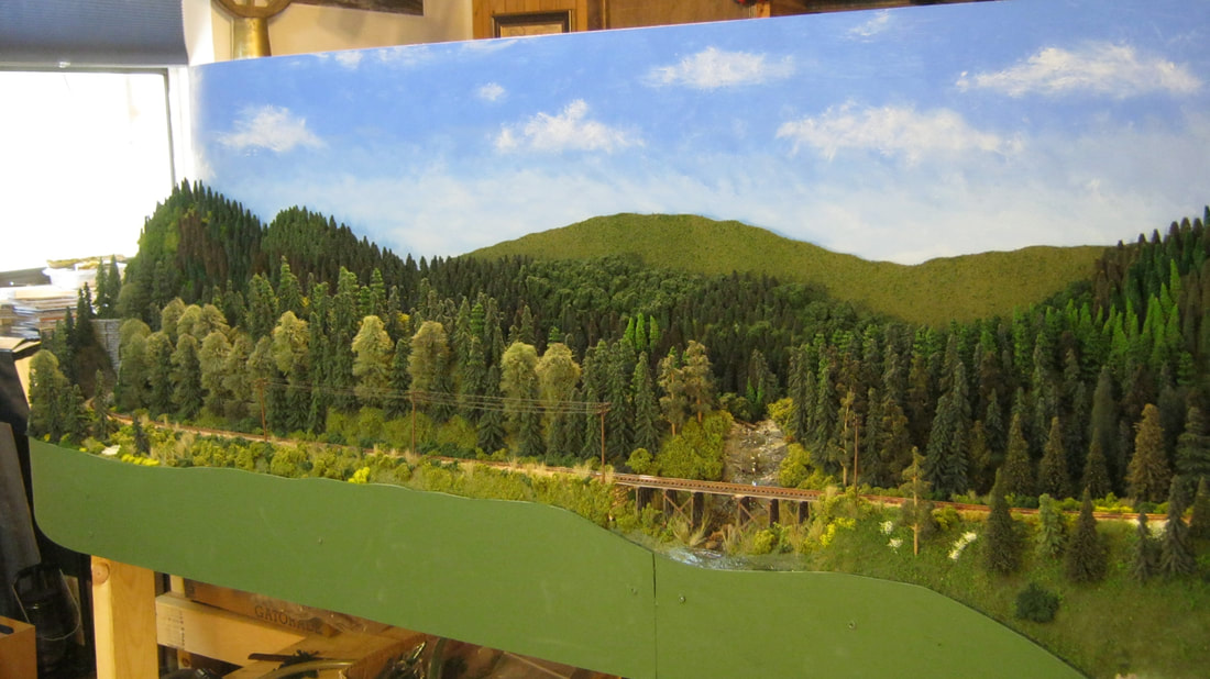
A double backdrop was installed, with the silhouette of a distant mountain being cut out of masonite, then covered with course ground foam, and inserted in between the rear hill and the backdrop of hand-painted sky with clouds. |
|
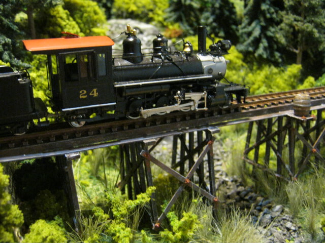
The final touches were adding a buck and doe into the stream bed below the trestle, and finishing filling the stream with Realistic Water, so the deer look like they're knee-deep in the stream.
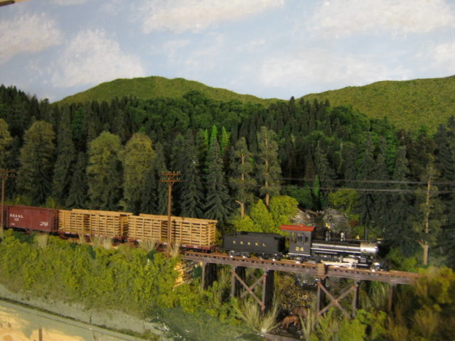
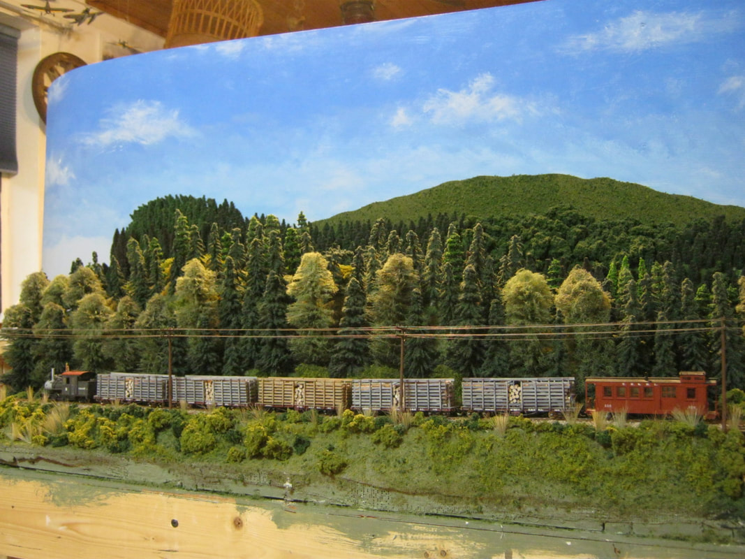
The Sluice Hill module is now ready to be added into the bigger layout, with SR&RL prairie #24 hauling a freight up the grade.
The Sluice Hill module is now ready to be added into the bigger layout, with SR&RL prairie #24 hauling a freight up the grade.
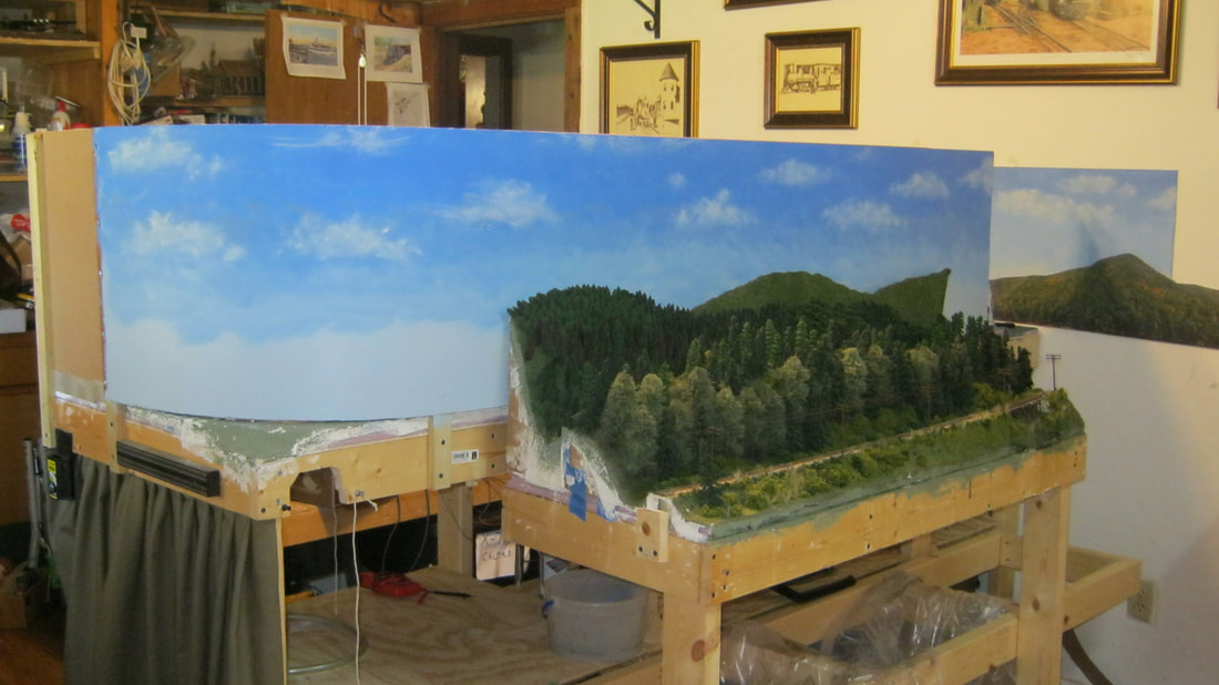
Above, you will see that I have now gotten ready to extend the track from Eustis Junction around the curve to the Sluice Hill module, which is a constant 3% grade down around another curve under the Rangeley model, continuing its 3% grade out from under Rangeley and onto the Reed's Station module. To give the curves a slightly better (bigger) radius, I put 1.5" spacer blocks of scrap wood between the back of Rangeley and the back of Sluice hill. I cut a full length 8' x 18" strip of Masonite, attached it and bent it around the back of the Rangeley backdrop, and painted the sky. I painted it two coats of light blue, then started at the top with a medium blue, adding light blue to the medium on the pallet as I blended the sky downward with a sea sponge. I then measured out the track radius on paper, and checked it out full size on the layout for the wooden ramp with track that would connect the whole thing up under the table.
|
|
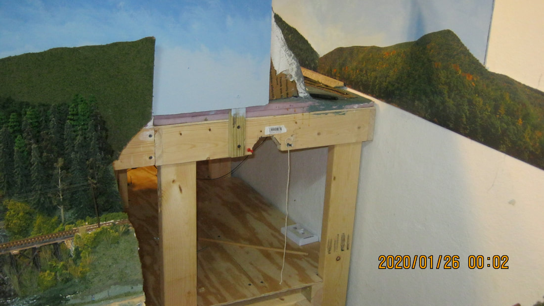
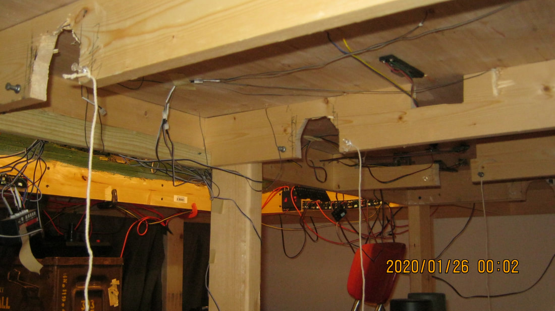
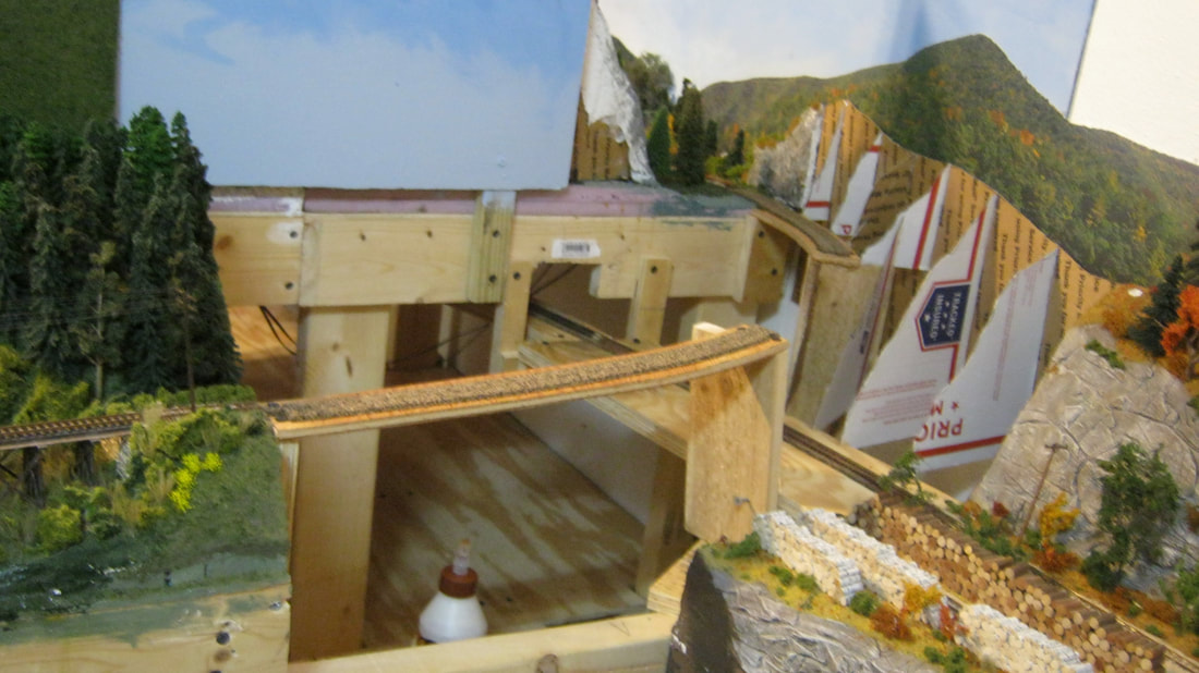
Above left is the joint between Eustis Junction behind the scenery in the upper center of the photo and Sluice Hill to the left of the photo. You can see the cutout in the benchwork where the grade will exit under Rangeley and continue to the lower right of the photo onto the Eustis module. The upper right photo shows where the ramp will leave Sluice Hill and disappear under the Rangeley benchwork.
|

|
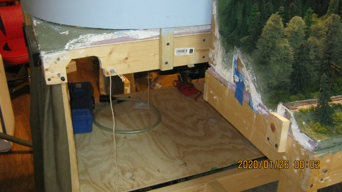
Above left are the cutouts in the benchwork under Rangeley. The push pins on both sides of the cutouts with the string hanging down are there to support the ramp, and adjust it at each point through the frames, until the ramp is at a true 3% grade before permanently bolting it into place. To the upper right is the completed ramp.
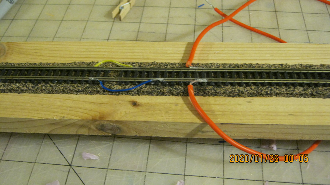
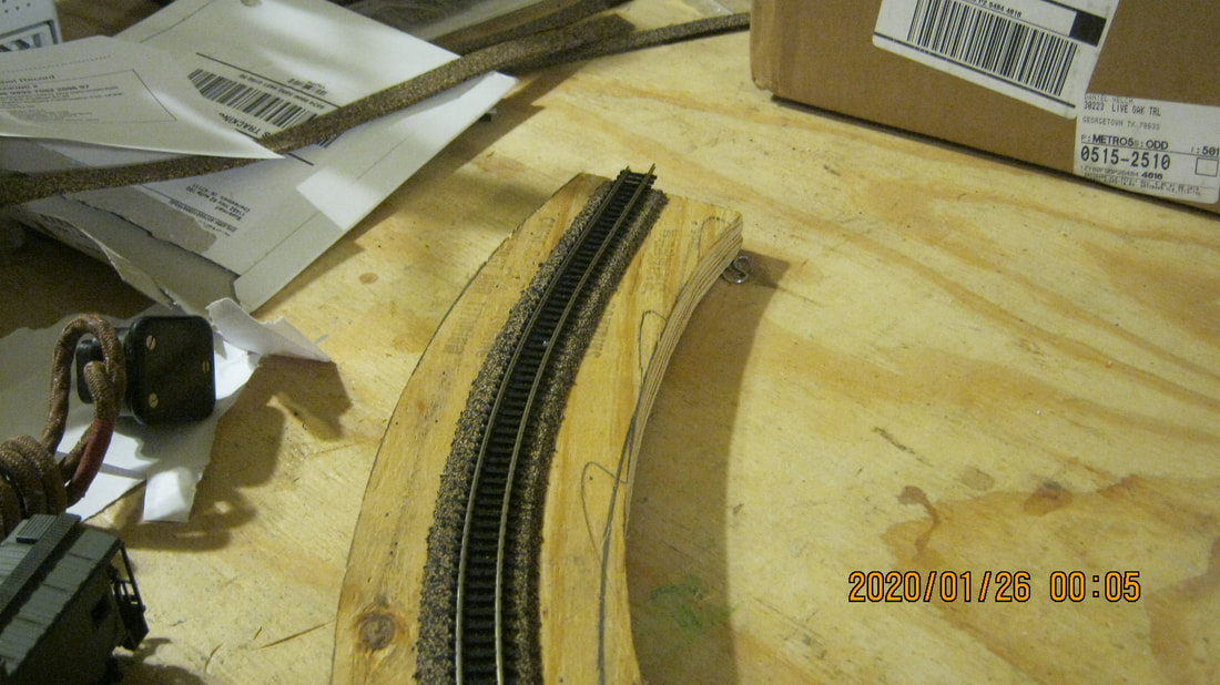
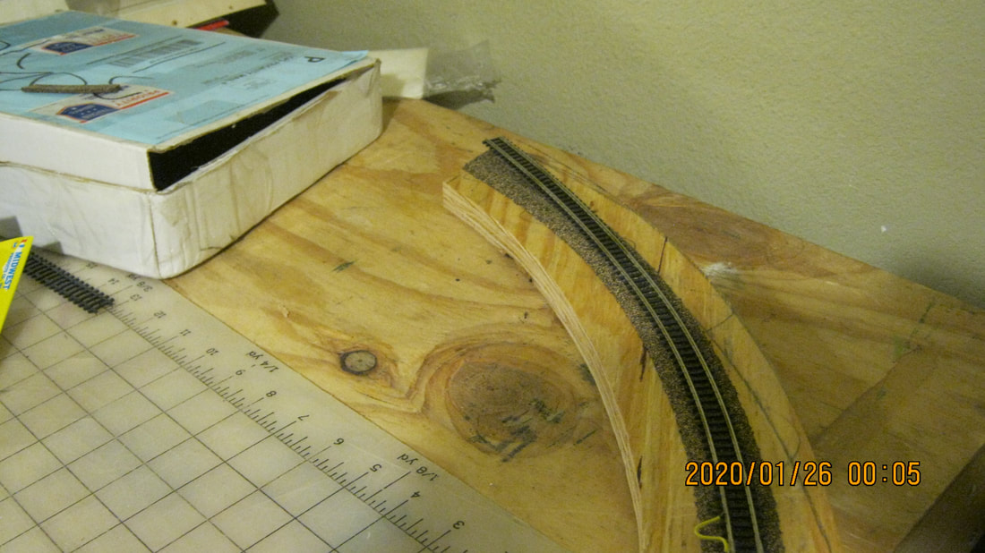
Below is the trackwork for the hidden track going down the ramp under Rangeley. To the lower left, you can see where I have soldered the power leads onto the track, and soldered leads connecting the rails at all the joints. I didn't solder the rails together to allow for expansion, with the leads ensuring good electrical contact between rails. None of this will be seen, so there is no effort to hide any of the leads. I laid cork roadbed to ensure a nice quiet ride under the layout. The lower center and right photos are the ends of the ramp that come out from under Rangeley to connect to Reed's Station and Sluice Hill. I left extra track extending off the ramp at each end that is not glued down to ensure an easy job mating up the rails with the other modules.
Below is the trackwork for the hidden track going down the ramp under Rangeley. To the lower left, you can see where I have soldered the power leads onto the track, and soldered leads connecting the rails at all the joints. I didn't solder the rails together to allow for expansion, with the leads ensuring good electrical contact between rails. None of this will be seen, so there is no effort to hide any of the leads. I laid cork roadbed to ensure a nice quiet ride under the layout. The lower center and right photos are the ends of the ramp that come out from under Rangeley to connect to Reed's Station and Sluice Hill. I left extra track extending off the ramp at each end that is not glued down to ensure an easy job mating up the rails with the other modules.
|
|
|
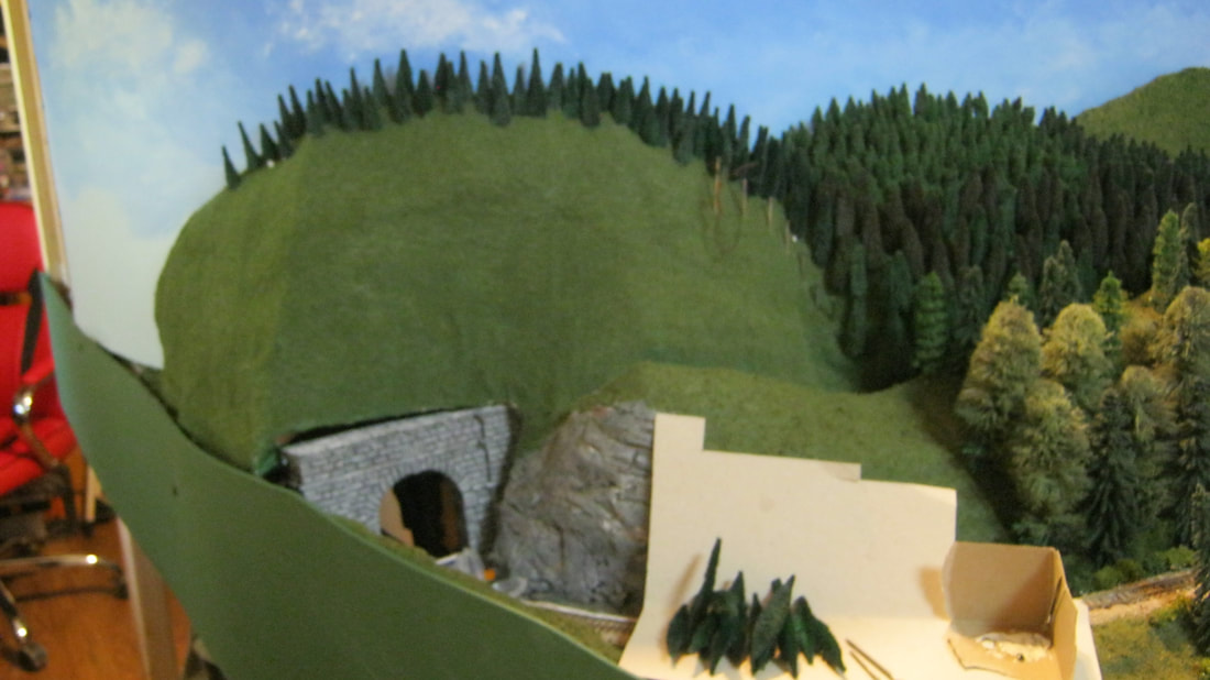
Above shows Sluice Hill permanently bolted in and ready for the ramp and extensions to the other modules ready to be built. The Reeds Station module is to the right, and is free standing for now. That way I can move it out of the way while working on the corner scenery between Eustis Junction and Sluice Hill, then move it back in and permanently bolt it in place to finish up the linkup with the track coming out from under Rangeley. The scenery in that corner will consist of a wooden trestle crossing over the Reeds Station track below, with the foliage beginning the transition to Fall. The scenery to the left of Sluice Hill will be a continuation of the same style of forest that is on Sluice Hill. These are the only two areas on the layout where something blatantly not on the original Sandy River and Rangeley Lakes Railroad will exist. I will try to make the end of the slope to the left of Sluice Hill disappear into the woods, with a tunnel entrance hiding behind the trees in case someone wants to get too curious where the train went. There weren't any tunnels on the SR&RL. There also were no trestles crossing over track below on the SR&RL, but at least it will look cool when it's done.
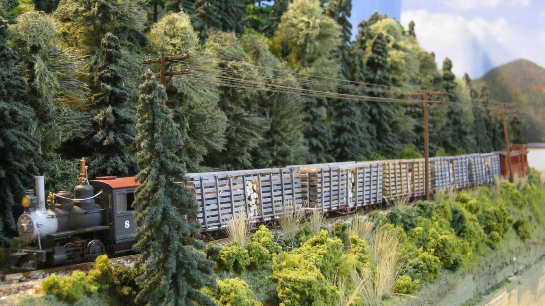
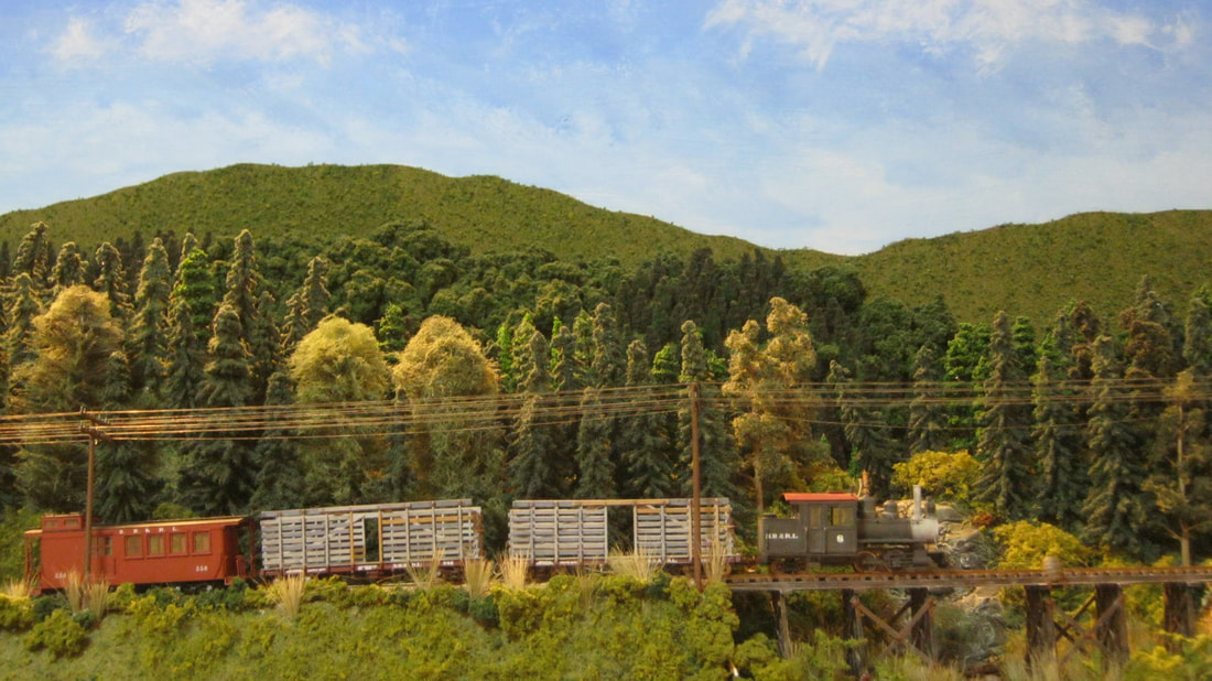
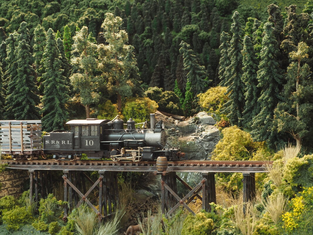
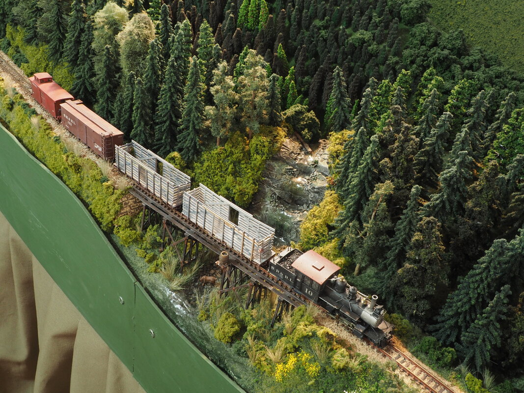
The above photo and the three below show #8 hauling a consist of five loaded pulp racks down the hill toward Phillips.
|
|
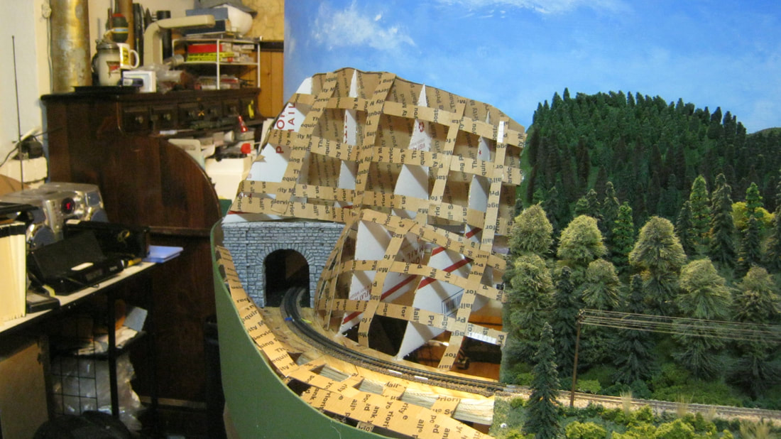
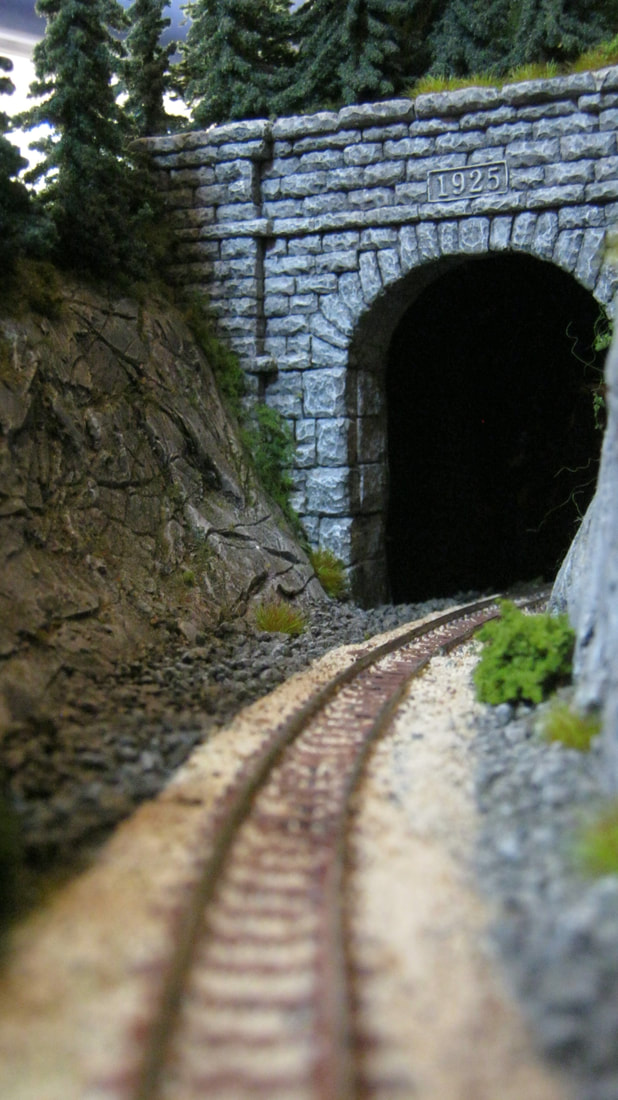
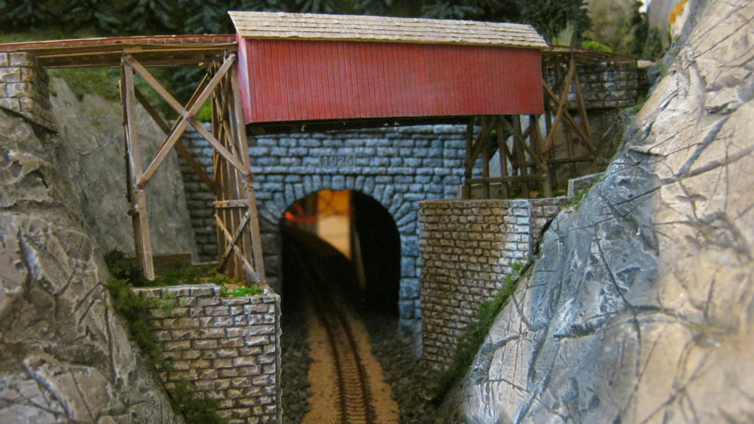
Above left, the commercial tunnel portal has been painted, black washed and dry brushed with Oyster White, and then set in place where I want the roadbed to enter the tunnel. The cardboard formers and strips have been hot glued into place around the portal, and are ready for plaster cloth. Above right, the track has been ballasted and painted, brown for the ties, and the rail sides on the visible side painted with rust. The whole roadbed and rails have been covered with painters' tape to protect them from the plaster cloth. The plaster cloth has been put in place, a minimum of two layers thick. Where I need extra strength, I apply three of four layers. I use wax paper held in place with mini clothes pins to protect the facia and the backdrop.
|
|
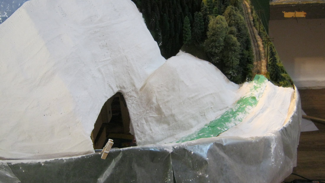
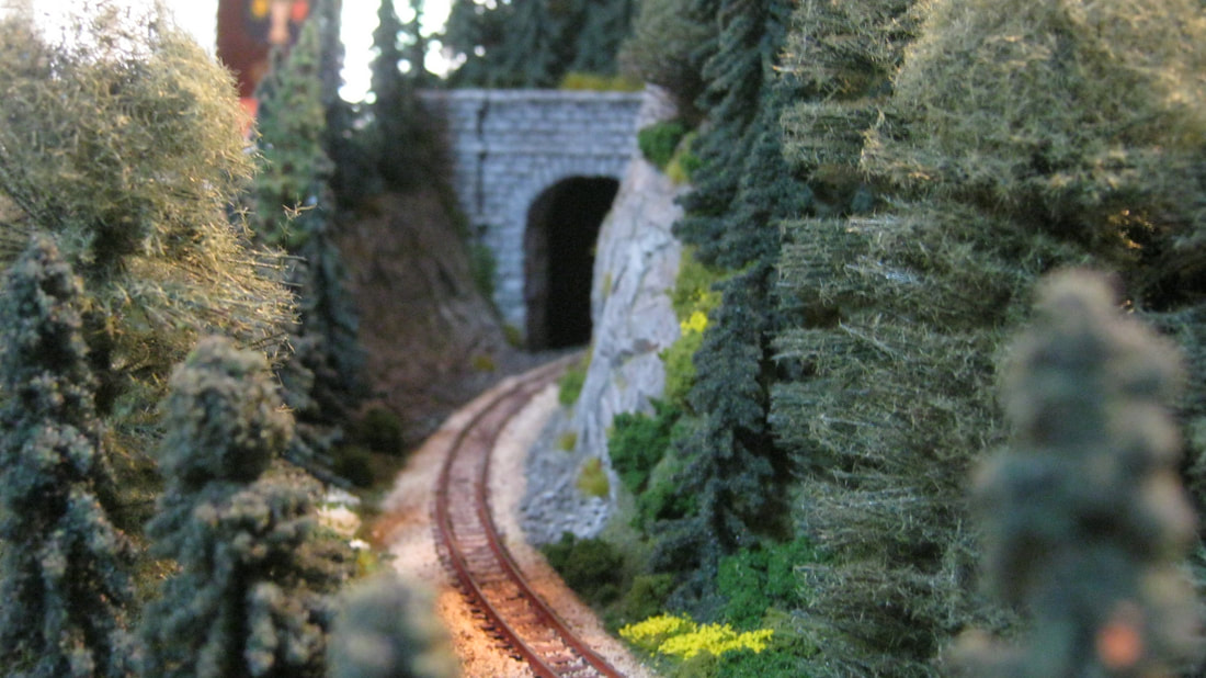
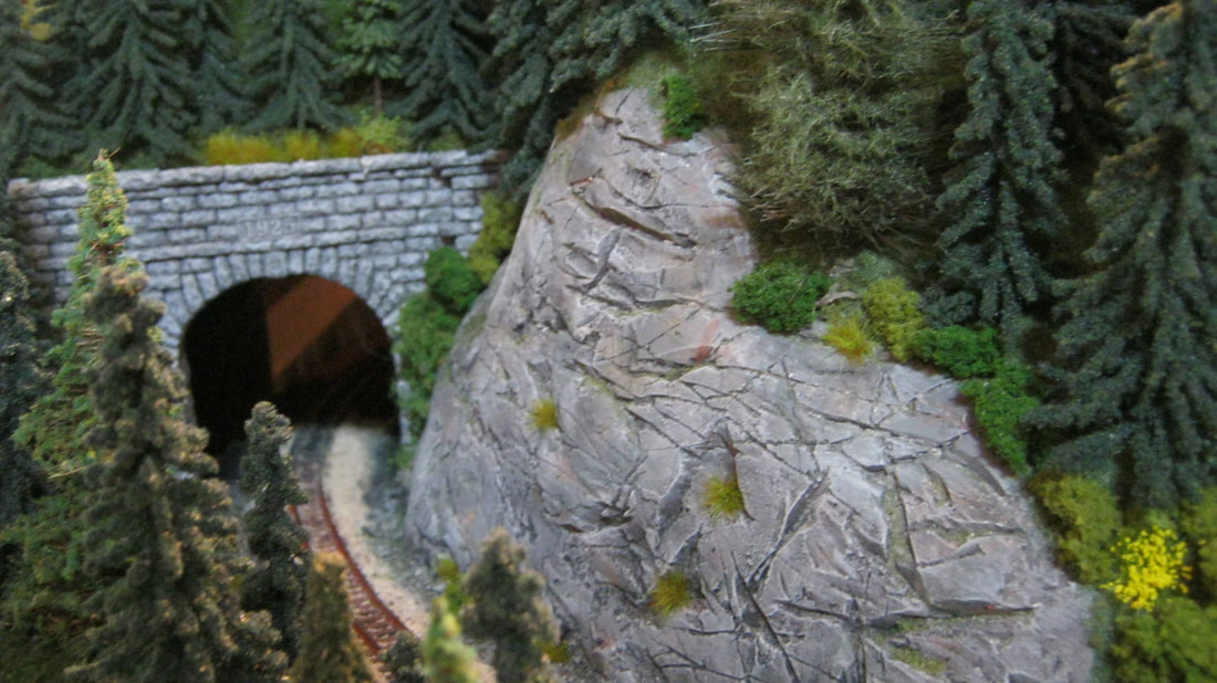
Above left, I have applied hydrocal plaster thickly on the left and right sides of the cut leading to the tunnel, and carved rock into the plaster. I then applied my usual black wash, then "damp brushed" raw umber, khaki, Hippo Gray and Cable Knit Gray over the rock, and finished it up with a dry brushing of Oyster White. After that, talus stained with a thick wash of Hippo Gray is spread at the base of the sides of the rock cut, to about 3" or so into the tunnel. Once all that is done, then I seal the rest of the plaster with green latex paint. After that's dried, another layer of green latex paint over the first to cover any missed spots, and shaking a mix of two shades of green ground foam and two shades of green flock onto the wet paint. Once that's dry, then planting evergreens on the "far" hill made from spray painted chenille bumps and deciduous "trees" that are just clump ground foam. The lower part of the "far" hill is covered with green poly material and ground foam.
After the "far" hill is done, then I put some stretched green poly material over the "near" hill, and start planting home made pines made from bottle brushes as well as a mix of Bachmann, JTT, and Grand Central Gems trees, two shades of green clump ground foam, and grass tufts, yellow and white flower tufts, a couple of tree stumps, and the left side of Sluice Hill is now done.
After the "far" hill is done, then I put some stretched green poly material over the "near" hill, and start planting home made pines made from bottle brushes as well as a mix of Bachmann, JTT, and Grand Central Gems trees, two shades of green clump ground foam, and grass tufts, yellow and white flower tufts, a couple of tree stumps, and the left side of Sluice Hill is now done.
|
|
|
The last thing I do, to double check the scenery, is take some photos of it, because the photos show me my mistakes and areas that need to be touched up. For instance, in the photo to the right, something I couldn't see with my unaided eye are the fibers sticking out from the poly material brush growing on the right side of the tunnel portal. Now I go in and correct that and any other flaws I find. The final touch will be extending the telegraph poles and lines across the new section of Sluice Hill up and over the hill to the left side of the tunnel portal.
|
|
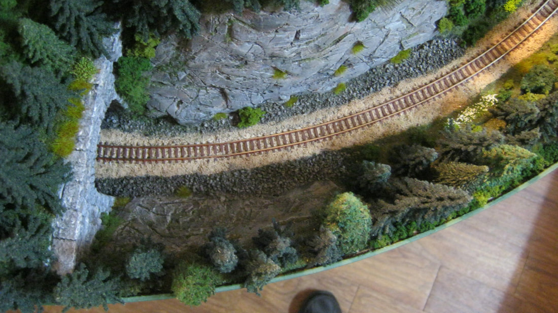
Below left, I have started on the right/north side of Sluice Hill, connecting it to Eustis Junction. I have marked the ends of the bridge, cut out that section of roadbed, put down the cork roadbed, and started building the structure for the hillside on the wall side of the track. Because of the way the track goes around that bend, and because I'm left-handed, I had to make that hillside, carve and paint the rock, and put on the initial ground cover there first. Then I did the left side of the track, extending the scenery from the finished section of Sluice Hill to the curve in the track. I did most of the trees on that back hill, then installed the track, and then the bridge, working my way from the farthest part of the scenery for this section to the nearest part on the aisle side of the layout.
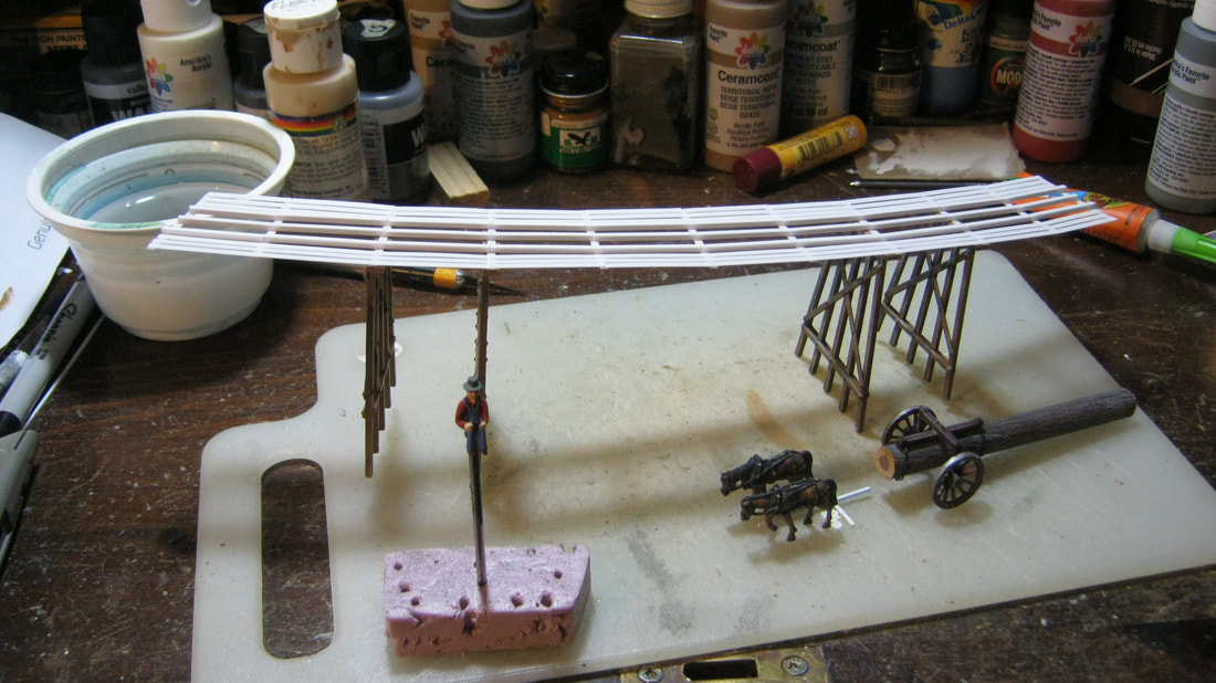
Below right, you can see this section about 1/2 complete. The piece of plywood is the section of the road bed cut out from where the bridge will go. The lines drawn on it are the centerline for the track, the edges of the ties, and the edges of the trestle bents. The bridge deck was built on this, so that it would fit exactly under the track when installed. Once the deck was built, the deck was taken off the plywood and turned upside down, and the superstructure of the bridge constructed on it.
Below right, you can see this section about 1/2 complete. The piece of plywood is the section of the road bed cut out from where the bridge will go. The lines drawn on it are the centerline for the track, the edges of the ties, and the edges of the trestle bents. The bridge deck was built on this, so that it would fit exactly under the track when installed. Once the deck was built, the deck was taken off the plywood and turned upside down, and the superstructure of the bridge constructed on it.
|
|
Below left is that corner portion now filled in, from the normal viewing direction of the operator. Forced perspective for the trees and hill top are used like the rest of sluice hill, with large trees in the foreground, and getting progressively smaller as they go up the hill. Bottom right is the trestle bridge in the process of being built. The log with logging arch, horse team and teamster are being finished up to go onto the Langtown module while sections of glue on the bridge cure.
|
|
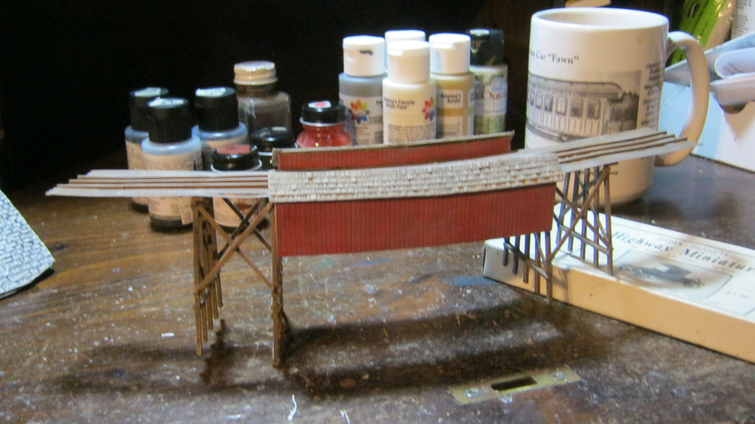
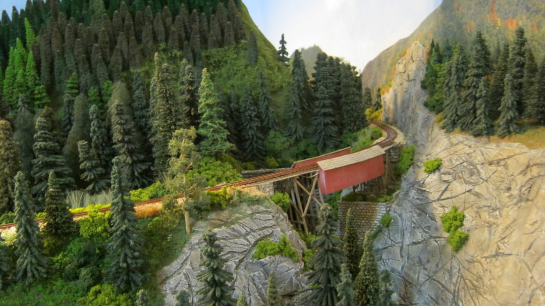
Below left is the bridge completed, with the covered span installed in the center. These covered spans were used in several places on the SR&RL, such as on Valley Brook Trestle. Below right are the trestle foundations that will be 'built into' the sides of the railroad cut.
|
|
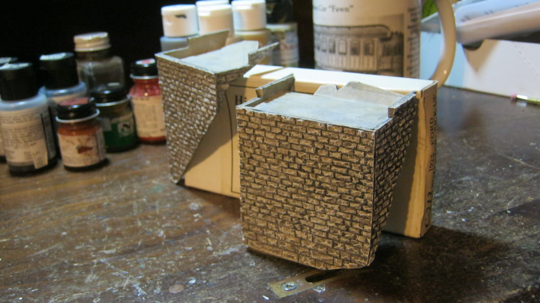
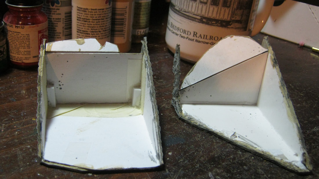
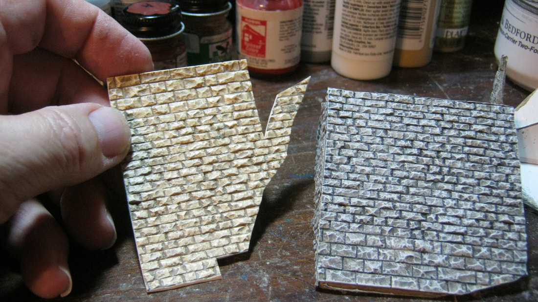
Below left, you can get an idea of how I made the foundations. I use heavy cardboard scavenged from F&C rolling stock kit boxes, which is good and stiff, and cut out a piece with a rectagular center the width and height of the foundation I need, with the sides the depth I will need at the top, and tapering down to the base of the center section. I then score them, fold them, and add a rectangular top, which you can see best in the left foundation in the left photo. I then test-place the foundation into the spot I need it, and start carving off sections until it fits properly into that spot. I add the flaps on the top and test place those and carve pieces off until the flap fills in the empty space between the rectangle and the stone side of the cut. As you can see on the right side foundation in the left photo, it required a LOT of carving until it fit into the railroad cut properly. Once these are done, I glue Chooch Enterprises stone wall material onto the outsides of them.
In the below right photo, the scrap piece of stone wall on the left is how the material comes, which is colored and weathered to look like limestone. I do a wash of dark gray over it, and when dry do a dry brushing of Oyster White over it to make it look like granite, which is what you see in western Maine.
In the below right photo, the scrap piece of stone wall on the left is how the material comes, which is colored and weathered to look like limestone. I do a wash of dark gray over it, and when dry do a dry brushing of Oyster White over it to make it look like granite, which is what you see in western Maine.
|
|
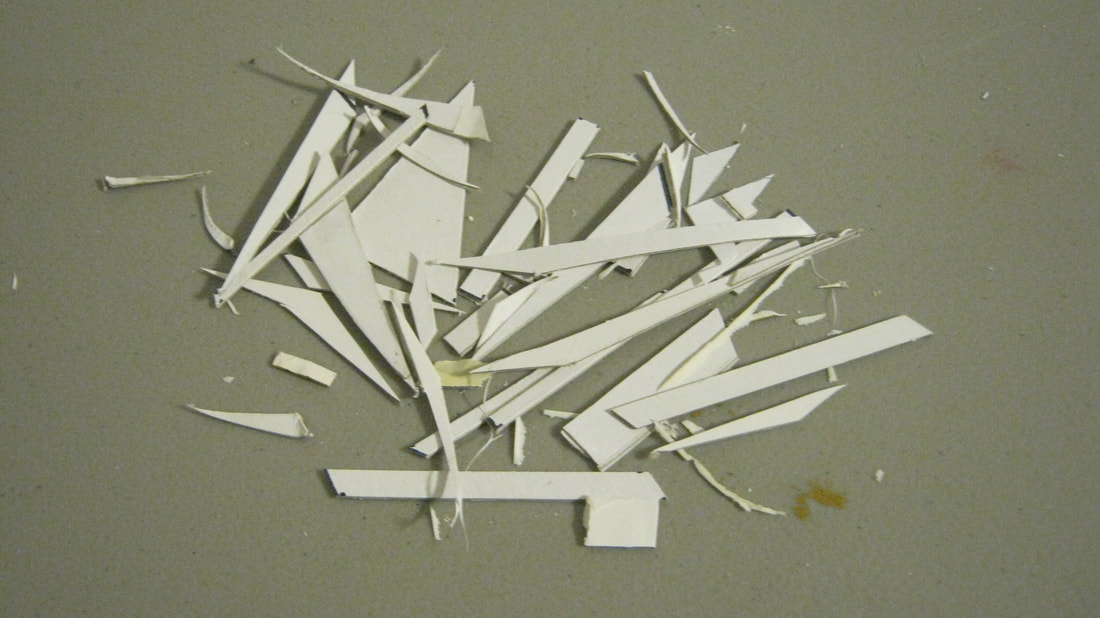
Below left is the scrap left over after the carving process for making the trestle foundations. This gives you an idea of how many times I put the foundation in place, decide what needs to be cut to fit, cut it, then test fit again and decide the next spot that needs to be carved off. I did this process with the bridge clipped in place, so that once the trimming is done, it they will fit properly under the bridge once it is permanently glued in place. It's a lot easier to simply make the abutments first then put the plaster cloth around them, but in this tight working space there's no way I could carve the rock around the abutments.
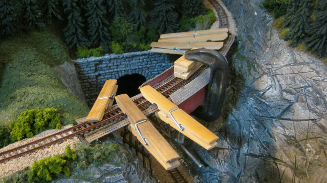
Below right, the bridge is now glued in place, to the bottom of the track, with epoxy, and held tight to it with clothes pins and c-clamps with wood blocks until the epoxy cures.
Below right, the bridge is now glued in place, to the bottom of the track, with epoxy, and held tight to it with clothes pins and c-clamps with wood blocks until the epoxy cures.
|
|
Below left and right, the bridge is now permanently in place, and the foundations are then put in place below it, snugged up under the trestle structure and against the stone walls of the cut. Super glue then permanently puts the foundations in place, and the bridge abutments up above are also glued in place, made the same way as the foundations. Once everything is dry, then foliage goes in to blend the joints of the foundations and abutments with the stone walls of the cut. Some of this is starting to be placed in the photo below right.
|
|
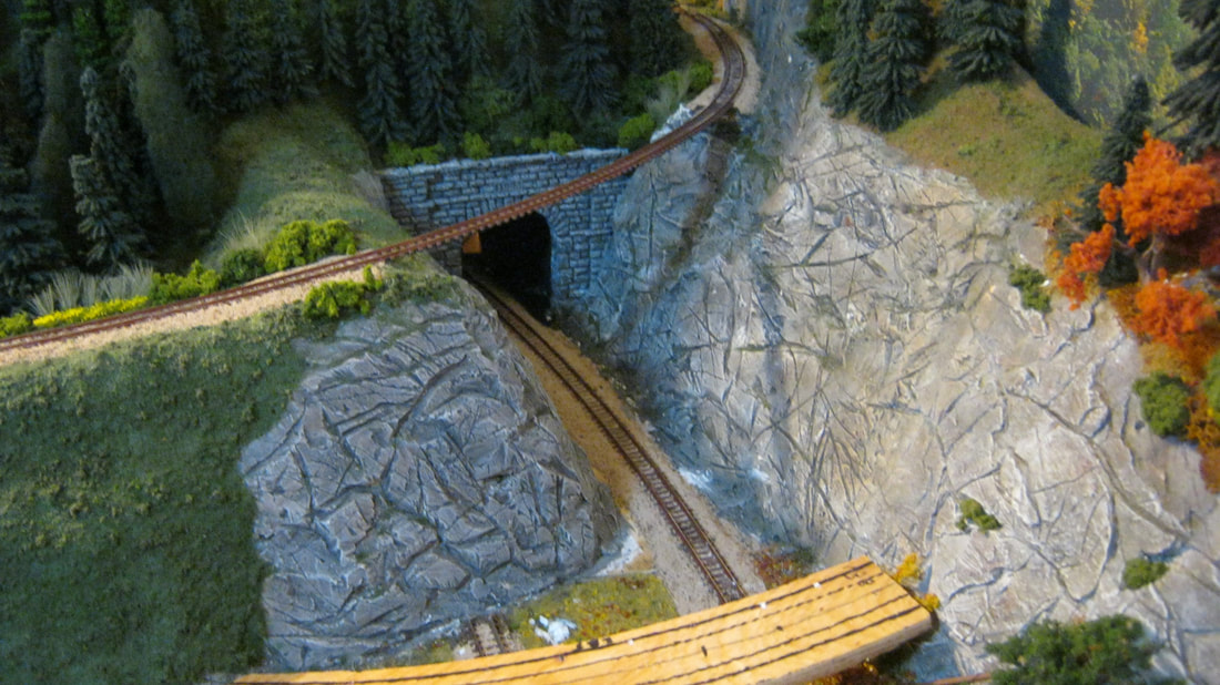
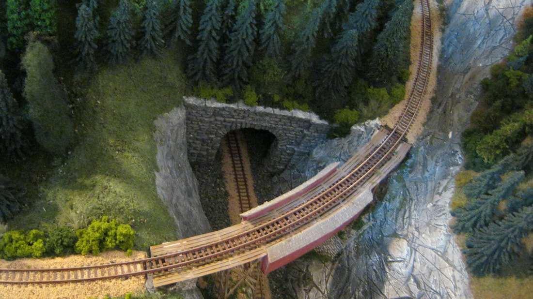
Seen below, the bridge is in now place, the foundations and abutments are in place, and the rest of the blending, scenery, track ballast, and weathering can be done to finish up this section of the layout.
Below, the detail of the "south" end of the grade is now done, and the only thing left to do is to finish replacing the the telegraph poles with improved ones and replacing the black telegraph wires with olive-green lines, now that I know that back then the copper was bare with no insulation, and turned green from exposure.
Below, the "north" end of the grade now done, minus the improved telegraph poles and lines, with scenery now blending it with the Reeds module to the right.
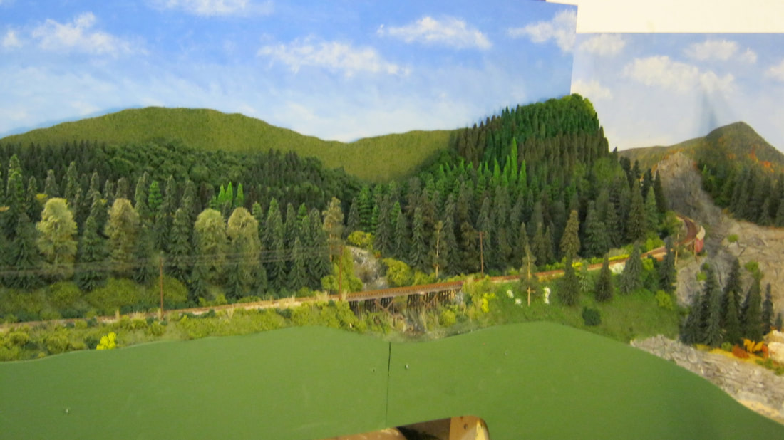
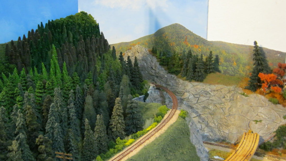
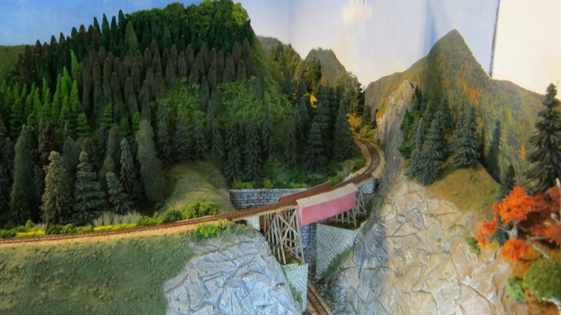
Below, the finished pass through the hills to Eustis Junction beyond. Since there was no spot on the actual railroad that had track crossing over itself like I had to do on the layout, this spot is "freelanced". Since it is freelance, I've named it "Grafton Notch", one of my favorite places from my youth, with "Old Spec Mountain" to the left, and "Table Rock" to the right.
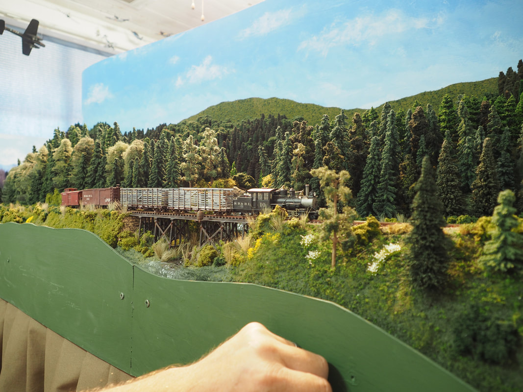
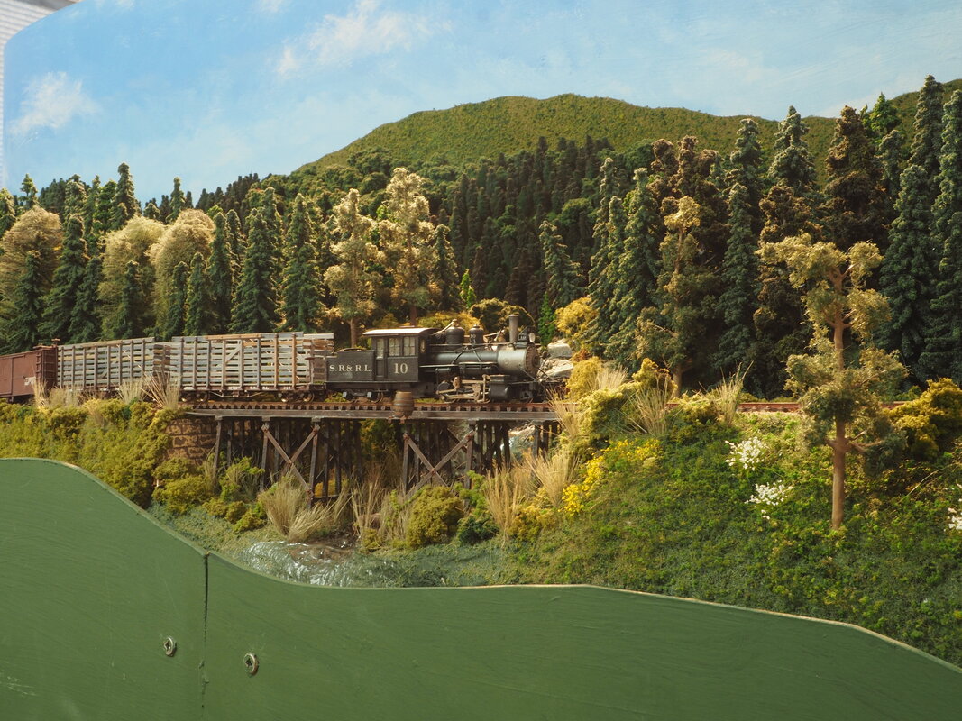
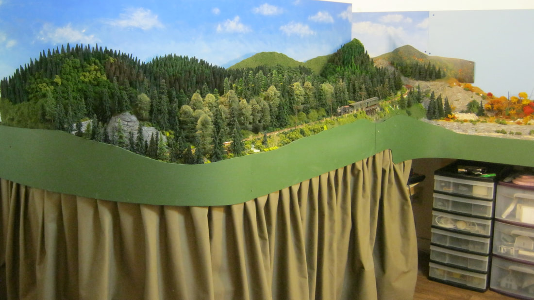
Below, the valance is now in place to pretty it up and hide the shelving below, and the first train to run down the now complete mainline between Eustis Junction and Reeds, is the Rangeley Express, being pulled by SR&RL #10.
|
|